Adding more magic to the Magicforce 68

This is a small journey on how I reverse engineered the MagicForce 68 keyboard and tried to add bluetooth functionality to it. It’s a small keyboard (68 keys, 65%) and is USB-only (it’s not the smart model). It has a controller that I can’t flash with a custom firmware, so I had to hook wires on it.
The Hardware
The first step in determining what I was against, was to at least partially disassemble the keyboard.
After the 6 screws under the keyboard and removed, the bottom cover is free and can be carefully removed as well (it has wires to the mini-USB connector board, so beware). The nice red PCB is now ready to be destroyed 😈
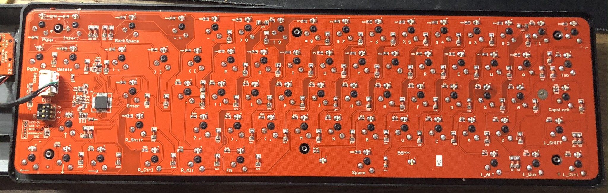
This is what I collected: It uses the Holtek HT68FB550 MCU - Datasheet - LQFP48 package
It exposes in the 5 pin header (bottom left on photo):
VCCGNDPA0/TCK1/OCDSDA- Used for debuggingReset/OCDSCK- Used for debugging & programmingUDN/GPIO0- USB D-, used for programming Debugging & programming are different procedures, according to the datasheet, they use different pins. But they refer to a “Holtek Writer” as the programmer AND debugger. I could find only the e-WriterPro. Seems fucked up (no docs, too expensive, not gonna work on linux/open source software, etc.).
It is a classic matrix-diode style keyboard, it gives logical 1 (5V if I remember correct) to rows and reads it from the columns (that way because of the direction of the diodes).
Matrix to MCU pin mapping (Rows: Top to Bottom, Columns: Left to Rigth):
| Pin Description | Pin | Name |
|---|---|---|
| NC | 42 | PgDown, PgUp, Insert |
| NC | 46 | Shift…, Up |
| NC | 44 | Tab…, Delete |
| NC | 43 | `123… |
| NC | 47 | Ctr…, Left, Down |
| NC | 45 | Caps…, Right |
| Pin | Pin Description | Name |
|---|---|---|
| 10 | NC | 9 |
| 34 | PA0/TCK1/OCDSDA | Left |
| 30 | PD5 | 4 |
| 14 | PD1 | ` |
| 7 | PE2 | 8 |
| 28 | PD3 | 2 |
| 29 | PD4 | 3 |
| 31 | PD6 | 5 |
| 36 | PA2/TP3_1/OSC2 | Delete, Up, Down, Right |
| 37 | PA3/TCK2 | Backspace, PgDown |
| 11 | NC | 0 |
| 26 | NC | =, PgUp |
| 32 | PD7 | 6 |
| 27 | PD2 | 1 |
| 33 | PE0/VDDIO | 7 |
| 12 | NC | -, Insert |
All LEDs have a common cathode on Pin 39 - PA5/SDIA/TP1_0 and a common anode to Vcc.
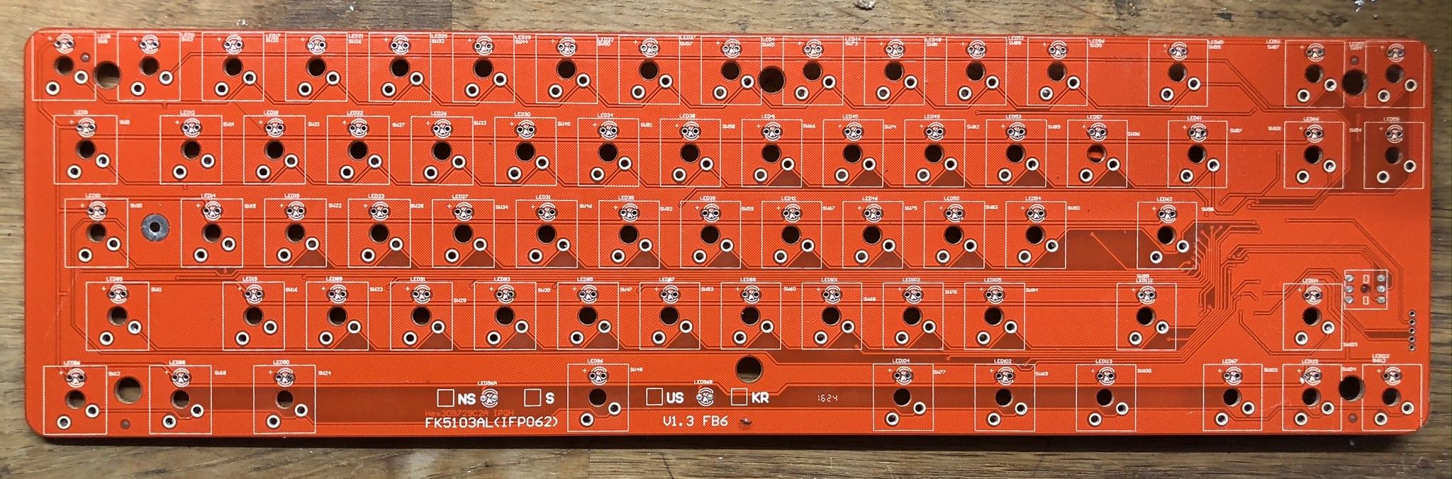
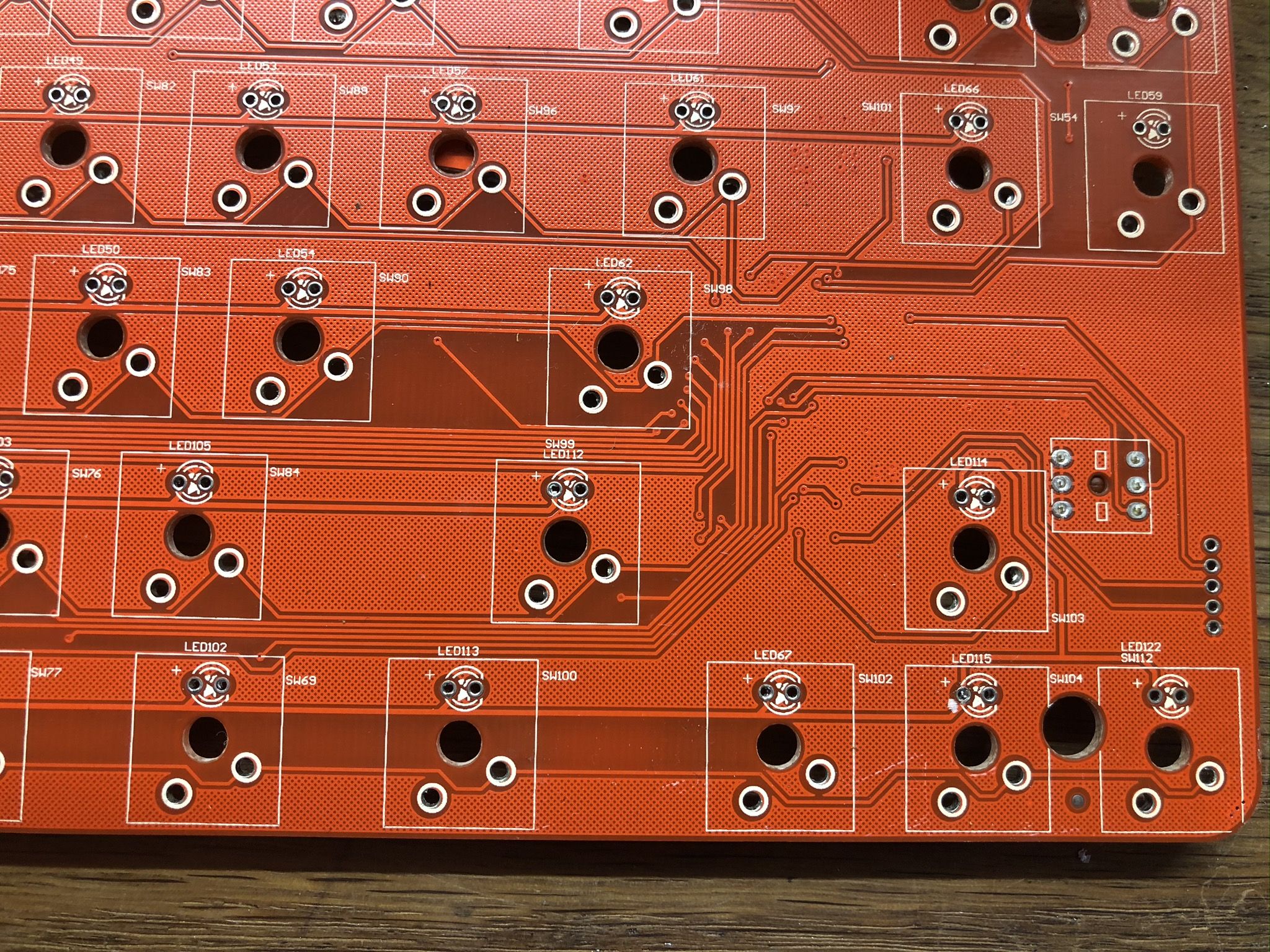
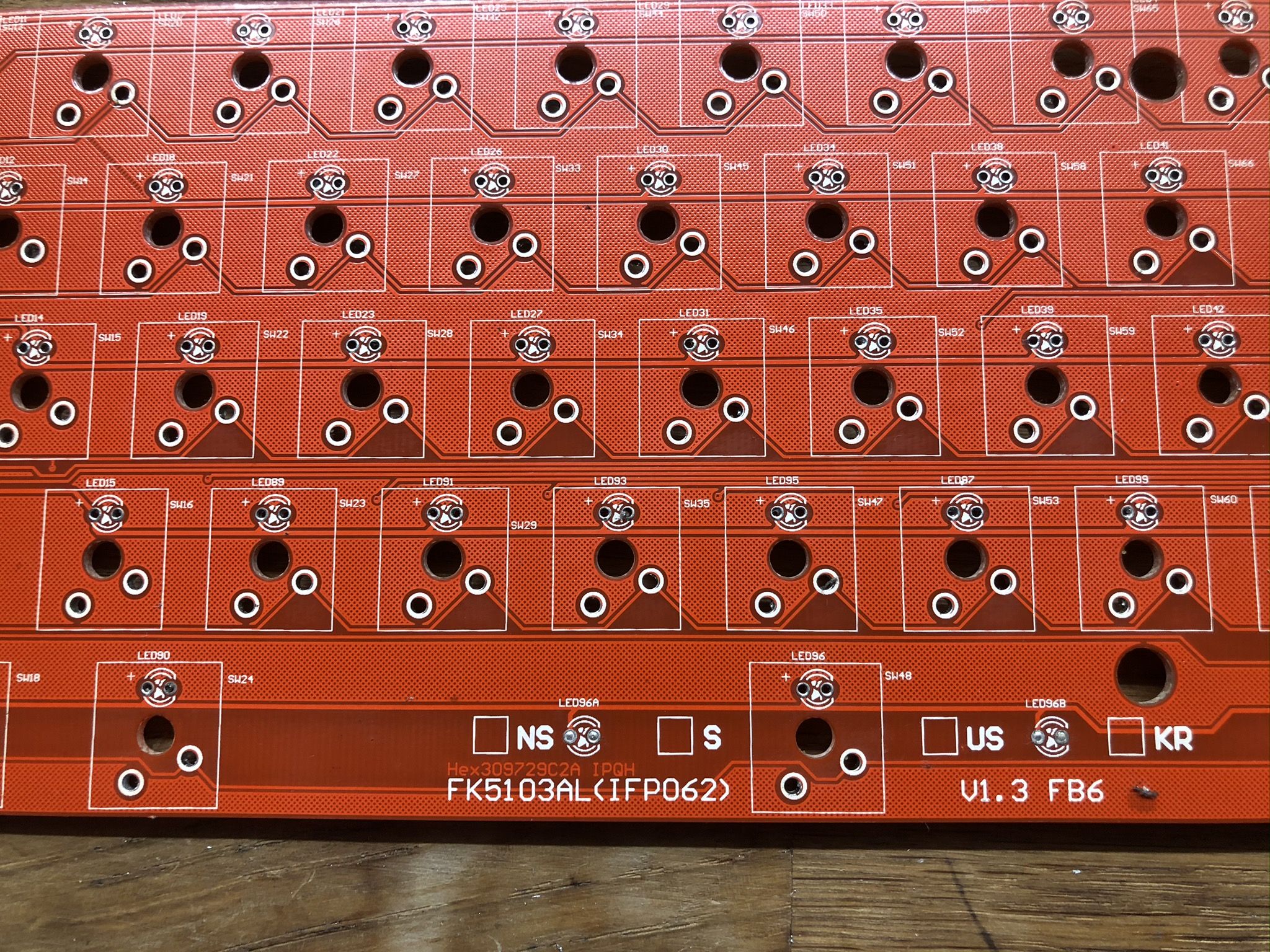
These are all the data that I gathered. Also, (spoiler) I ended up desoldering all of the switches to create my own keyboard so I got access to the front of the PCB. It’s empty, but it’s VERY time consuming to remove all the buttons so here are some photos:
{{% gallery %}}
{{% /gallery %}}
The hack
Ok, so now we know what we’re up against. But what now?
The idea begun with my frustration with wires - right, bluetooth. But how?
I had an Adafruit Feather Bluefruit at hand, based on the marvellous NRF52832. I love the NRF52 family, but after a bit of research I learned that the 52832 does not have USB support and does not have a “CryptoCell”, which means a crypto accelerator which mean no BLE Secure Connecttion. The NRF52840 offers all these goodies (while the BLE SC support for arduino is under development at the time of writing) but I had to spend money before even having a PoC. Let’s get to work with the 52832!
There was a side idea, that apart from the regular bluetooth keyboard functionality to add U2F and/or GPG SmartCard support. So I started searching if anything like this exists
- OpenSK: Written in Rust (🎉) but does not support at all the 52832 and Rust support for the NRFs is pretty useless (maybe I’ll revisit this at some point)
- QMK support for my microcontroller - nope
- Any github project with over 200 commits that is a keyboard implementation for my MCU, preferrably in MicroPython - none
- MicroPython that led me to this and was a no due to the problems with FS & other unsupported features - nope I was forced to write the whole firmware from scratch in Arduino. Ugh… “Δε γαμιεται…” (roughly translates to “Fuck it…” in Greek). I’ll do it. I’ll hook the rows & columns of the keyboard, connectt them to my MCU and control them. I was sure that the on-board MCU won’t interfere (it did) and it’ll work like a charm (it didn’t) and I’ll throw in an OLED as well (I didn’t). But before that, let’s write & test the firmware. Then I’ll solder wires on the PCB.
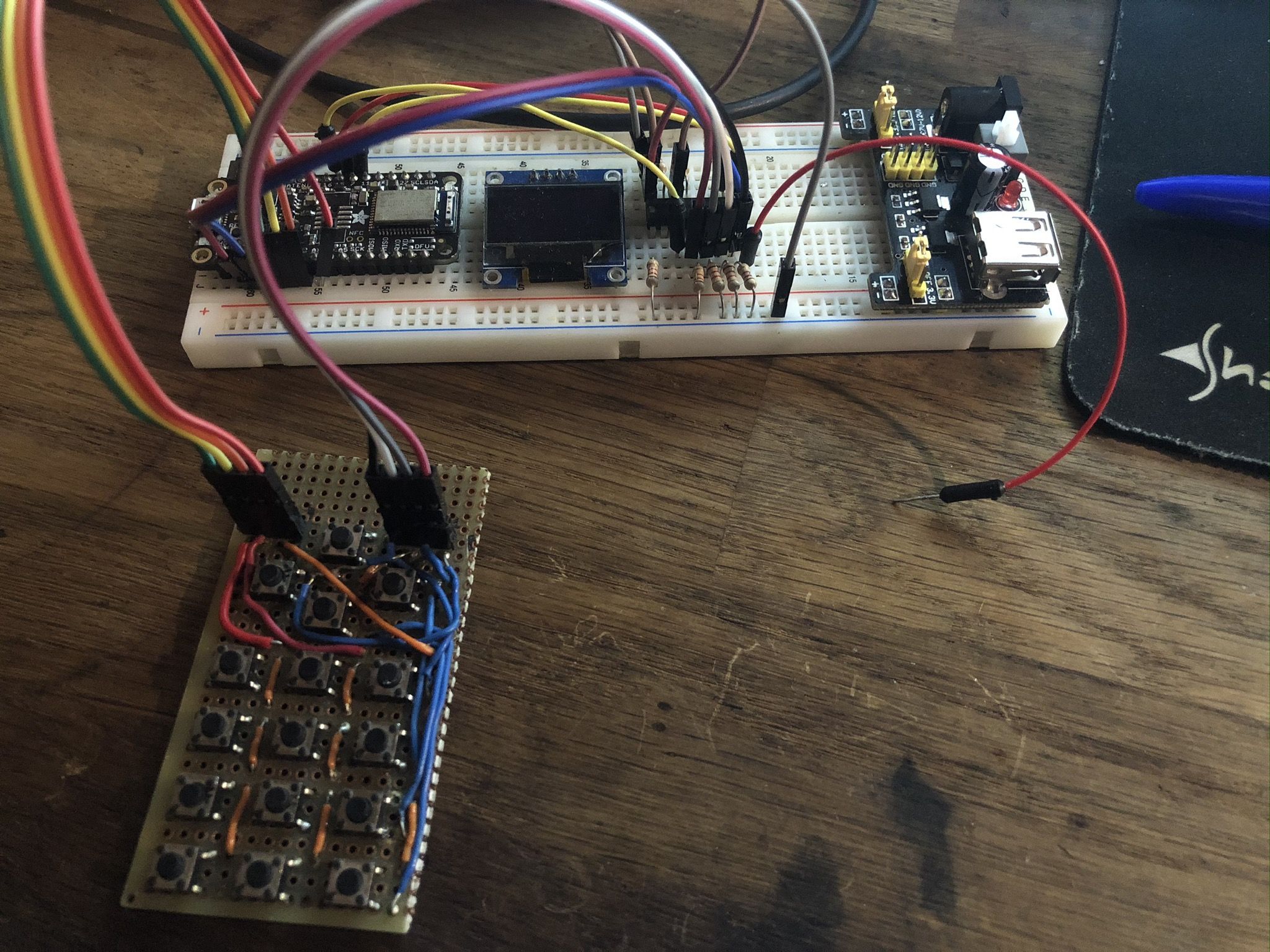
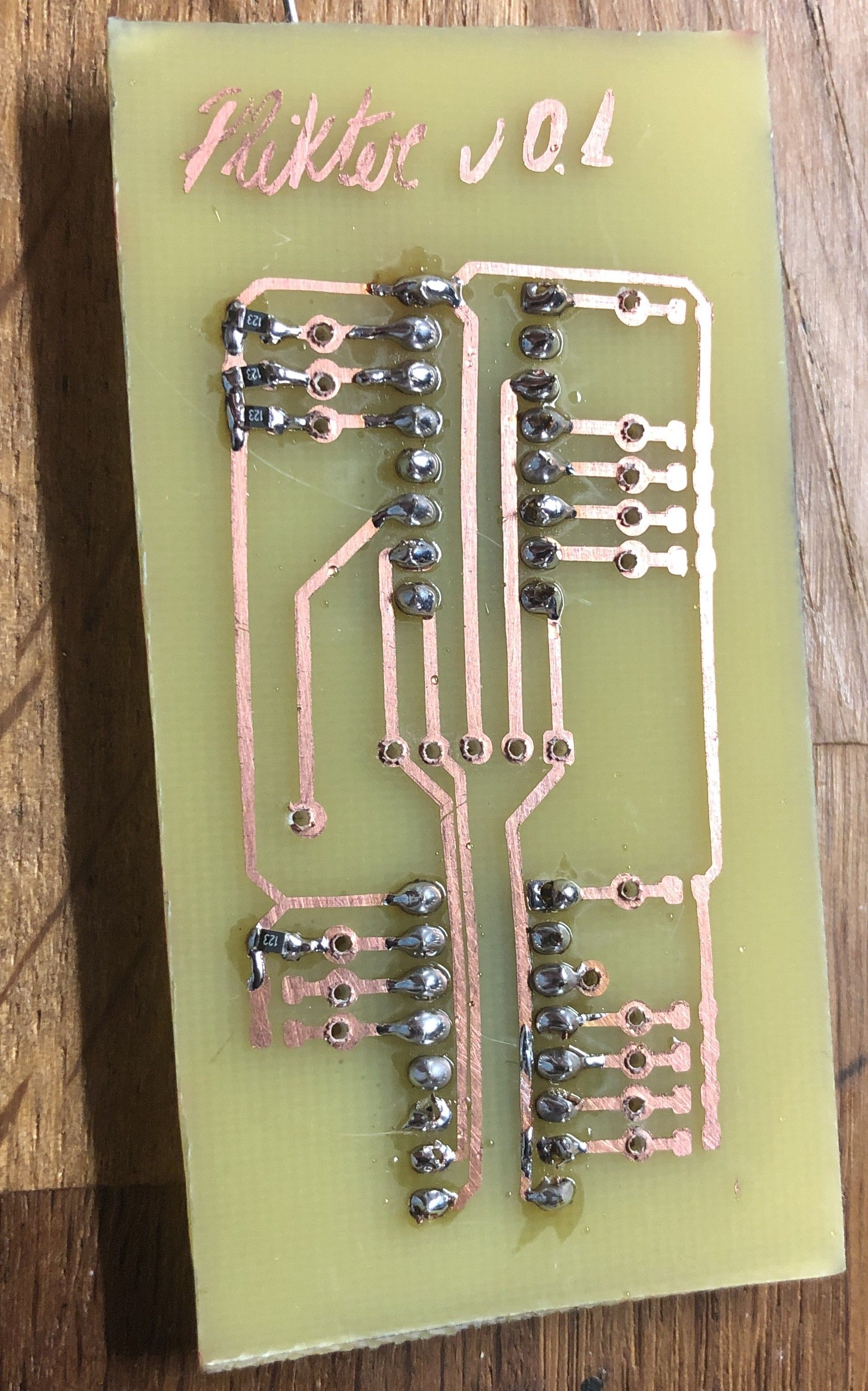
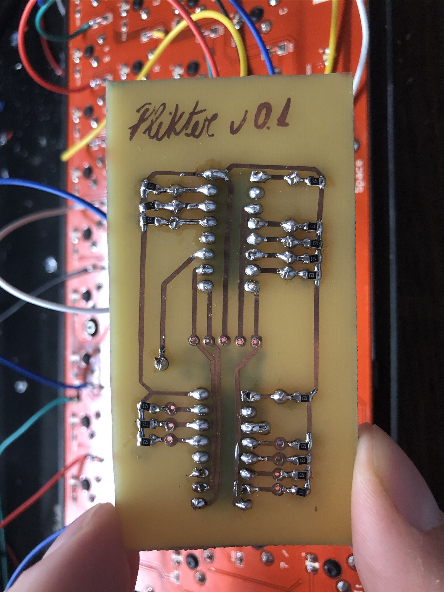
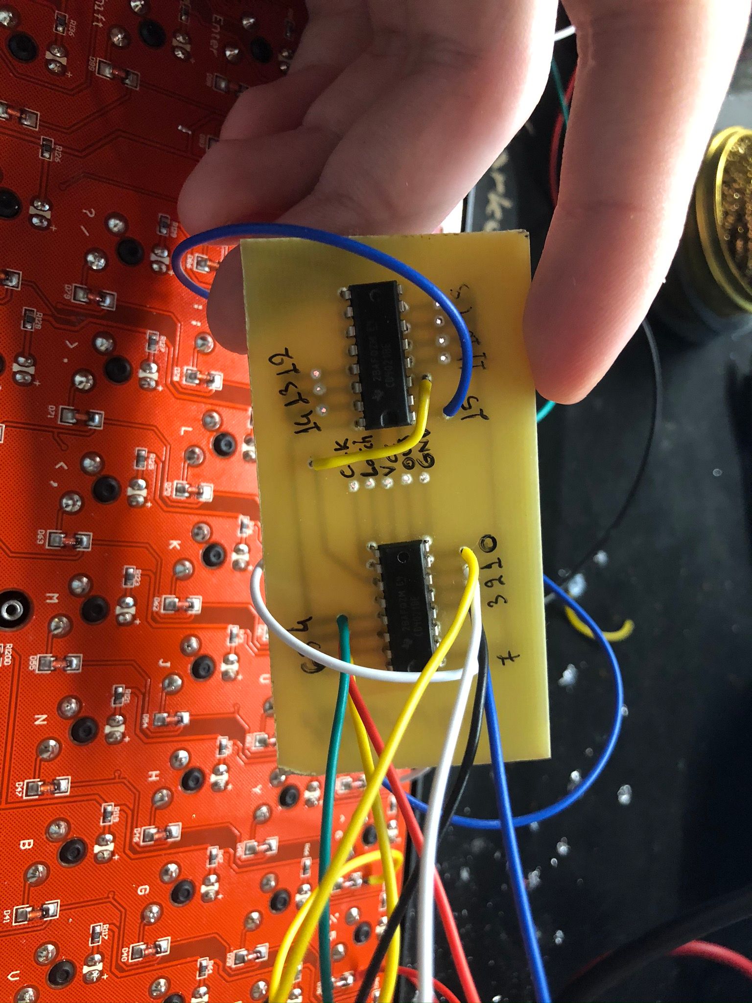
There you go, Plikter. It is comprised of the firmware that runs on the feather and 2 daisy chained shift registers (TI CD4021BE) that read the columns as there are not enough pins on the feather - and of course these are on a custom board whose gerbers you’ll find in the repo - made with a plotter following the etching method described perfectly by stavros. Soldering time!
{{% gallery %}}
{{% /gallery %}}
The outcome
It didn’t work.
I debugged it and I think that the internal resistors on the ports of the keyboard MCU that were connected to the rows & columns were interfering, but I’m not sure.
Anyway, I had a (mostly) ready firmware & hardware for a keyboard and I was too frustrated by flying USB wires on my desktop. I made the SiCK-68, but that’s a story for another time.
Hope you had fun!